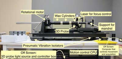
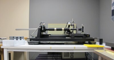
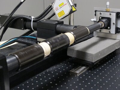
The UC Berkeley Library version of the scanning machine. The machine is shown loaded with three cylinders. During a scan the probe begins at the left and is moved to the right in 1.8mm steps using precision motion controls. Because the probe is all the way to the right in this image, it is shown at the end of a scan. The black table is "floating" on pneumatic isolators that keep a layer of air between the workbench and the white table underneath. This prevents small vibrations, even those which may not be palpable or perceptible to humans, from vibrating the system and effecting measurements.
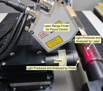
The image shows the probe and the laser on the scanning machine. The probe measure the height at 180 points on a surface in its range. The probe can only focus on a surface in its .35 mm range. Wax cylinders typically have deformations in their surface or have some elliptical eccentricity on the order of 5mm. If the probe remained stationary then the cylinder would wander in and out of its range as it rotated. To compensate for this, the laser, whose 25 mm range is far larger than the out of roundness of the cylinder surface, measures the height of the cylinder as it rotates and relays that data to a focusing motor that moves the probe closer or farther from the cylinder to ensure that the surface stays in its range.
The image shows the probe and the laser on the scanning machine. The probe measure the height at 180 points on a surface in its range. The probe can only focus on a surface in its .35 mm range. Wax cylinders typically have deformations in their surface or have some elliptical eccentricity on the order of 5mm. If the probe remained stationary then the cylinder would wander in and out of its range as it rotated. To compensate for this, the laser, whose 25 mm range is far larger than the out of roundness of the cylinder surface, measures the height of the cylinder as it rotates and relays that data to a focusing motor that moves the probe closer or farther from the cylinder to ensure that the surface stays in its range.
The UC Berkeley Library version of the scanning machine. The machine is shown loaded with three cylinders. During a scan the probe begins at the left and is moved to the right in 1.8 mm steps using precision motion controls. Because the probe is all the way to the right in this image, it is shown at the end of a scan. The black table is "floating" on pneumatic isolators that keep a layer of air between the workbench and the white table underneath. This prevents small vibrations, even those which may not be palpable or perceptible to humans, from vibrating the system and effecting measurements.
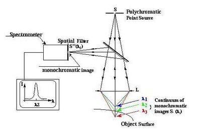
This diagram explains the operating principle of the confocal microscope. At each of 180 points, white light is shone through a series of lenses which split the light into constituent wavelengths such that different wavelengths focus at different heights in the probe's range. When a surface is placed in the probe's focal range, the light that is incident, reflects off the surface, is gathered and analyzed. By analyzing the intensity of the wavelengths in the collected light, the probe can detect which wavelength of light was in focus on the surface and from this can calculate and output the height of the surface.
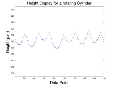
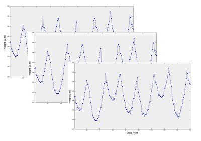
The image is a plot of the data measured by the probe on the scanning machine. The probe measures and reads out the height of a surface in its range at 180 points on a line 1.8mm wide. This plot results from measuring a 1.8mm line on a cylinder. The groove intersects the line several times as it winds around the cylinder and so shows up as several crescent shaped dips in the height of the surface.
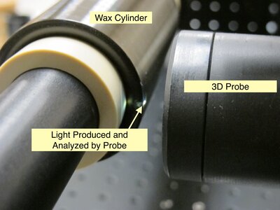
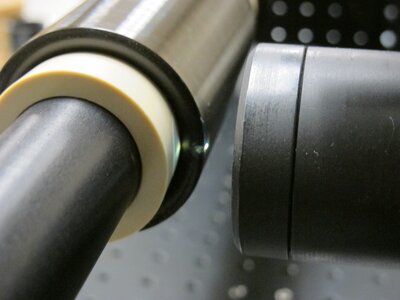
A close up of the probe (the black cylinder at the right of the image) and a cylinder loaded on the machine (the brown cylinder on the left of the image). The probe shines a white light that is 1.8 mm wide (visible as the white line on the cylinder) and analyzes the intensity and color of reflected light to find the height of 180 points on a surface.
This method is meant to illustrate how data collection works for a cylinder. During acquisition, individual measurements of the height at 180 points along a line are taken in quick succession, at slightly different positions, as the cylinder rotates, and then stitched together in analysis software.